Audio Buffer - originally issued in May 2002
Output circuits of standard signal sources as CD players suffer from limited capability to drive capacitive load and low impedance load. Depending on signal cable length (capacitance) and amplifier input resistance/capacitance there is an interaction between output circuits of CD player and the cable. This may result in a loss of resolution of high frequencies, harsh (grain) sound and soft undefined bass. The following circuit may solve the problem and can be also used as a high quality headphone amplifier. It has high input resistance and low capacitance and low output resistance. It is able to deliver output current of some 250mA. The frequency range is far beyond audio needs. The distortion is very very low, order of 0.0001%. This circuit should be connected to the CD output by coaxial cable no longer than some 10 - 15cm.
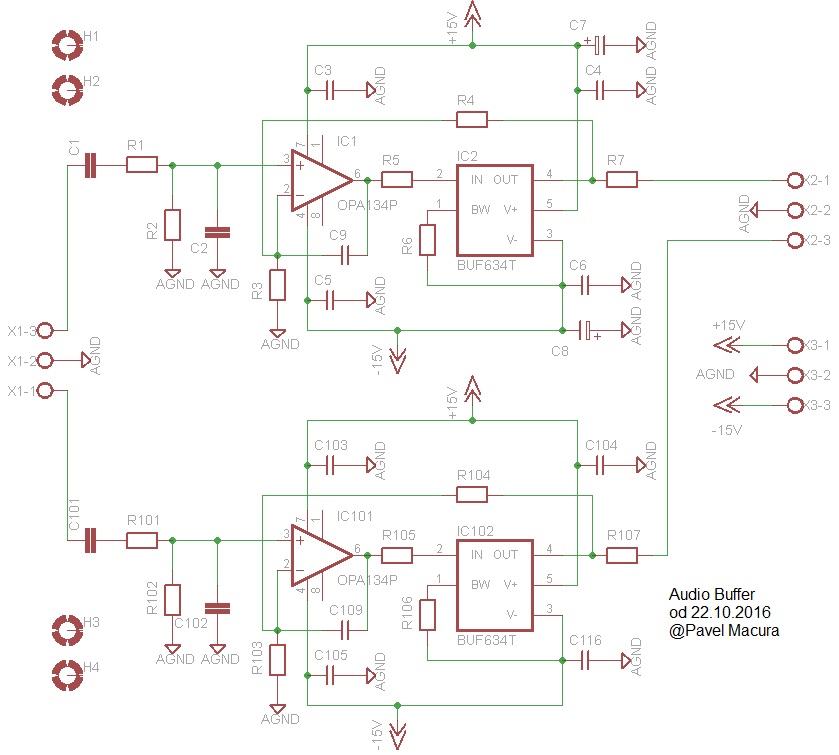
Following image shows the Audio buffer circuit after it was modified in October 2016:
As op amp IC1, OPA134PA, LT1122, OPA627AP and AD825 were tested. The best results were obtained with OPA627AP on IC1 position, but this op amp is 10x more expensive than OPA134PA. The second amp IC2 is Burr-Brown fast buffer BUF634T. The whole circuit has a voltage gain of +1, acts as a buffer amp and the influence of output cable is eliminated. The load resistor Rt (terminating resistor) is optional. Voltage gain with Rt = 50 Ohm termination is +1, without termination +2.
Higher Iq
The circuit as shown operates at quiescent current of 8mA. This current can be increased by reducing R6 to 0R (wire jumper), then Iq=15mA and buffer mostly operates in class A even for 50 + 50 ohm load.
Photos of completed audiobuffer


Printed circuit boards are not available now.
Documentation is on the link
Parameters
Measurements of harmonic distortion (2022)
THD and THD+N at 1kHz

THD and THD+N into 50 ohm load

RightMark measurement protocol
Audio Buffer was measured with a measuring system consisting of Topping D10s DAC and E1DA Cosmos ADC. Here you can find a comparison of the measuring loop (DAC ==> ADC) parameters and the same loop after insertion of the Audio Buffer. One can see that the influence of the Audio Buffer to the system parameters is neggligible.

Headphone Amplifier
The same circuit can be used as a headphone amp. The R4 can be enlarged up to 24k to obtain higher gain. One should use a potentiometer of 10k before C1, preferably the blue Alps.
January 2020 headphone amplifier update
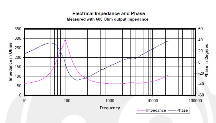
I am updating my recommendations for a headphone amp. The best results are with R7 completely omitted, output impedance is then close to zero, with AD744 at X1 it is 0.056 ohm. This eliminates influence of headphones impedance to resulting frequency response. I have Sennheiser HD598 headphones with impedance plot as below and the improvement when omitting R7 is substantial.
With R7 set to zero, not every opamp may be used and stability is to be checked. My current setup is with R3 = R4 = 1k5 and IC1 = AD744. The difference of R7 = 0 compared to R7 = 100 ohm or 50 ohm is stunning, re sound accuracy from headphones.
created: May 2002
last updated: January 4, 2023.