Capacitor distortion
Capacitors are one of the basic passive elements R, L, C. Though inductors are not so often needed in our electronic circuits, resistors are mandatory and capacitors are frequently used as bypass supply capacitors, in signal paths as coupling capacitors and in filters.
We may have quite strict requirements on capacitors placed in a signal path if we ask for lowest possible nonlinear distortion of the signal. Nonlinear distortion created in capacitors depends mostly on the dielectric material used. We can observe nonlinearity related to frequency, signal amplitude, temperature or mechanical pressure. My test is concentrated on capacitor distortion related to capacitor loading (load impedance), to frequency and to voltage amplitude.
4 types of capacitors are investigated - aluminum electrolytic (unipolar and bipolar), tantalum electrolytic, high K ceramic X7R and MKT polyester film. 3 different test circuits are used. As a signal source serves Topping D10s DAC, for measurements E1DA Cosmos ADC is used.
Test circuit #1
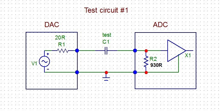
Output from the DAC is connected to the capacitor under test C1 which is connected to the input of the ADC. Input impedance of the ADC is 930 ohm, by measurement.
Fig.1. Test circuit #1
Capacitors under test:
As a most revealing test, THD vs. frequency distortion measurement was used, with a sine sweep from 20Hz to 22kHz and measuring bandwidth 45kHz. Measurements were made at 1.75Vrms DAC output voltage. Fig.2 shows frequency response with both capacitors in the measuring loop and for the direct DAC-ADC loop without tested capacitors. Fig.3 shows THD vs. frequency plots for both capacitors and for the DAC-ADC loop.
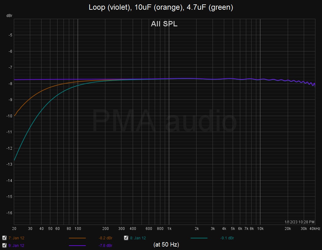
Fig.2. Frequency response of the DAC-ADC loop, loop with 10uF capacitor, loop with 4.7uF capacitor
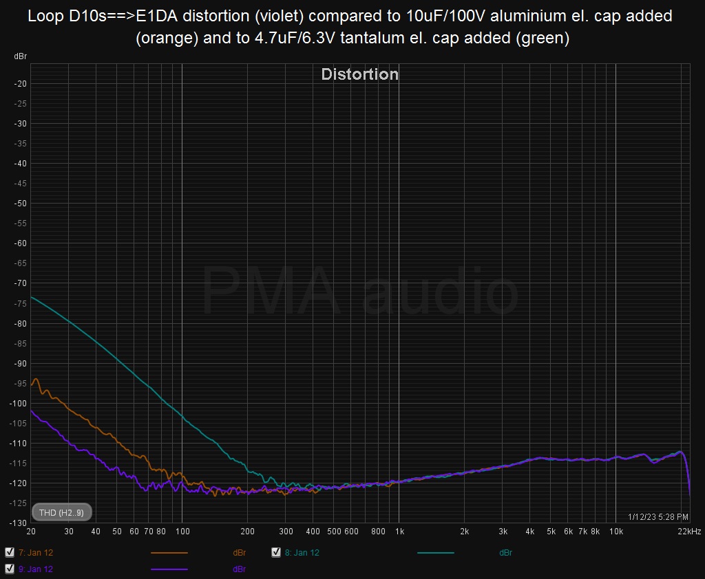
Fig.3. THD vs. frequency of the DAC-ADC loop, loop with 10uF capacitor, loop with 4.7uF capacitor
We can see that both electrolytic capacitors add low frequency (LF) distortion, which starts to rise below 300Hz with the 10uF aluminum capacitor and below 150Hz with the 4.7uF tantalum capacitor. But we can also see the rise of LF distortion below 70Hz for the DAC-ADC direct loop, which is most probably a result of input ADC electrolytic capacitor distortion, because the input impedance of the 1st opamp in the ADC is quite low.
Test circuit #2
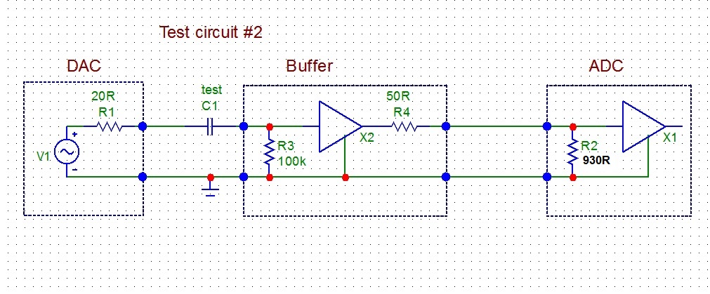
In the previous test (#1) the capacitors under test were loaded by quite low input impedance of the ADC, 930 ohm. Let's allow much less difficult load of the same capacitors. It will be 100 kohm instead of previous 930 ohm. For this reason, Audio Buffer with 100 kohm input impedance, 50 ohm ouput impedance and gain = +1 is inserted into the measuring loop as a capacitor load. Please see Fig.4.
Again, THD vs. frequency was measured and the capacitors under test were:
The test voltage was 1.7Vrms. The result is shown in Fig.5.
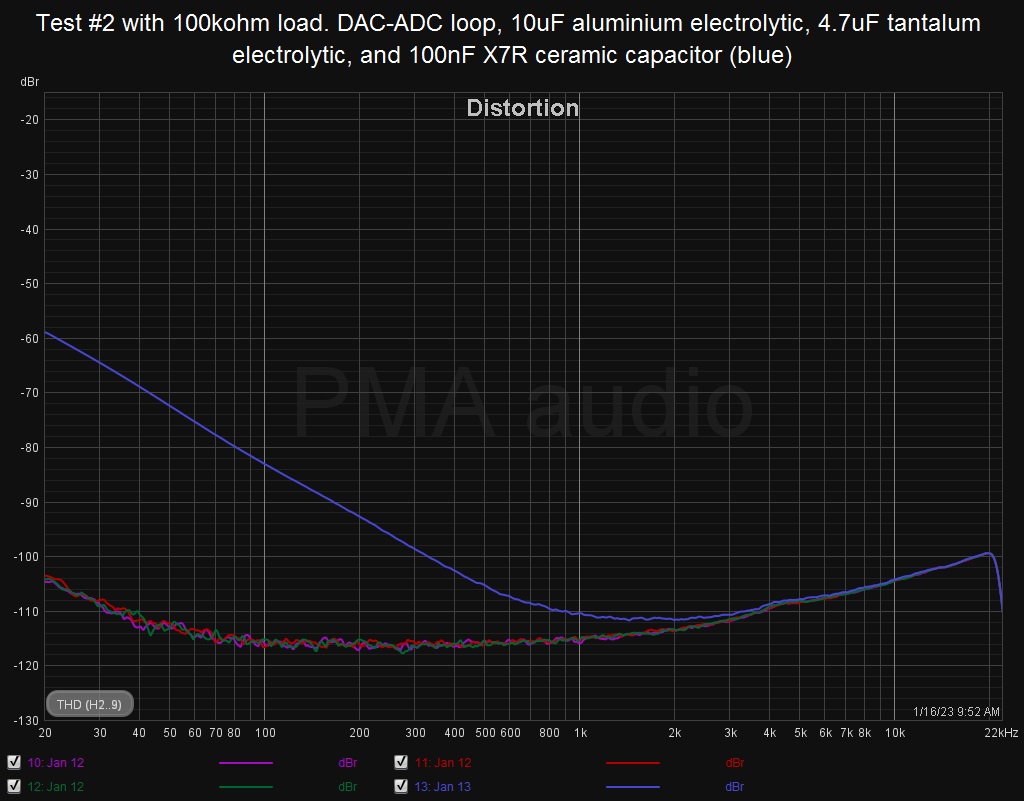
Fig.5. THD vs. frequency with 100kohm load
We can see now that with the light load of 100kohm, the distortion plots of the loopback and 10uF and 4.7uF capacitors do overlap. The only exception is distortion plot with the 100nF X7R capacitor, which shows high LF distortion, starting as soon as below 1kHz, though the CR filter -3dB corner of the high-pass (100nF+100kohm) filter is at 15.9Hz. Please avoid high K ceramic capacitors (like X7R) in the signal path!
Test circuit #3
The last test compares distortion of a bipolar electrolytic capacitor composed of anti-series connection of two 47uF/35V aluminum electrolytic capacitors (resulting in 23.5uF capacitance) with distortion of the polyester foil MKT capacitor 22uF/250V=. Capacitors under test are now loaded with 50 ohm resistor and driven from 50 ohm output impedance of the Audio Buffer (Fig.6). Low frequency -3dB corner of the high pass filter 22uF+50ohm is now 72Hz/-3dB.
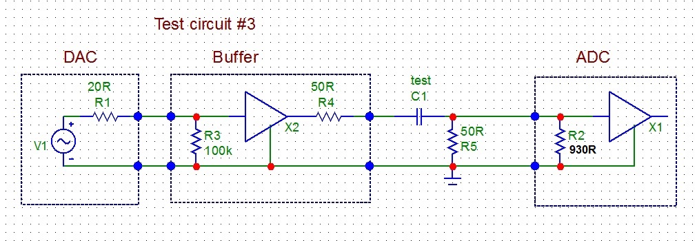
Fig.6. Test circuit with 50 ohm load
Capacitors under test:
In Fig.7 we can see THD vs. frequency distortion plots for both capacitors, at 0.9Vrms from Audio Buffer output.
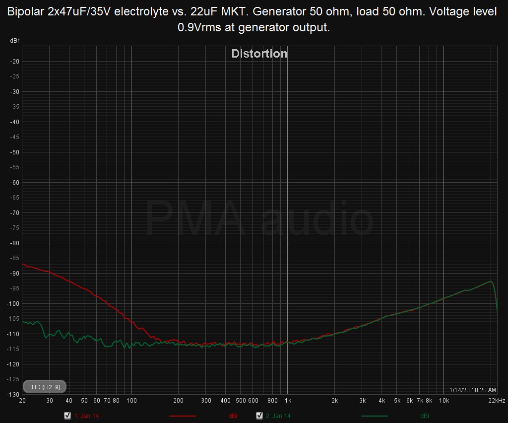
Fig.7. 22uF MKT capacitor distortion (green) vs. bipolar 47uF+47uF electrolytic capacitor distortion (red)
The MKT foil capacitor brings no LF distortion, however the bipolar electrolytic capacitor adds LF distortion below 150Hz.
Conclusion
The tests have shown that electrolytic capacitors do not add LF distortion if their are lightly loaded, in other words if there is negligible ac voltage across these capacitors. High K X7R ceramic capacitor adds high level of nonlinear distortion even if moderately loaded. High K ceramic capacitors should be completely avoided from audio signal path. MKT foil capacitor does not add LF distortion even if it is loaded by low impedance. It can be used in filters, and electrolytic capacitors of all kind (even the bipolar ones) should be avoided in filters.
@Pavel Macura, 01/2023