Hypex UcD180HG HxR module analysis and measurements
After buying and testing AIYIMA A07 amplifier (based on TPA3255 class D chip) in January 2021 I was disappointed with the frequency response modulated by speaker complex impedance and its audible consequences. This is, unfortunately, inevitable for the class D design with output LC filter outside the feedback loop, because the LC filter response damping not only depends on load resistance, but also LC filter impedance interacts with connected speaker complex load impedance, which may modify the frequency response even more. This was confirmed by measurements of A07 frequency response into various speakers and into speaker dummy load. So I was seeking for a different class D topology (and not only hysteresis switching with PFFB) that would have affordable price and would be free of the mentioned frequency response modulation by the complex load. Yes there are Ncore and Purifi modules that are close to amplifier perfection, but they are quite expensive, NC400 module would cost 349.00 EUR (incl. Tax), without a power supply. So I started to review another options and turned my attention to the older UcD design, namely UcD180HG HxR, the latest datasheet [1] link is here:
I ordered the module from Audiophonics France at the following price: UcD180HG HxR module at 115.96 EUR, 4-pin Hypex signal cable at 8.97 EUR, shipping 13.71 EUR, total price 138.64 EUR incl. tax.
Hypex UcD180HG HxR description and analysis
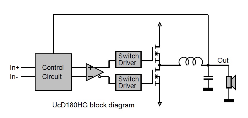
Block diagram of the UcD180HG is shown in Fig.1 (from [1])
Fig.1. Block diagram of the UcD180HG module
We can try to make a circuit analysis in MicroCap circuit simulator, starting with a circuit diagram as shown in Fig.2 which is based on information published in paper [2]
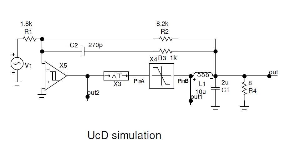
Fig.2. Circuit simulation of the UcD module
It is a self-oscillating circuit with phase-shift control using the reconstruction filter L1,C1 and phase lead network R3,C2. The frequency of the self oscillations would be at the point where loop gain phase shift is 180°, see plots in Fig.3.
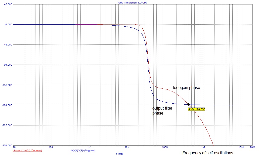
Fig.3. Loopgain stability analysis
The feedback is taken from the load, behind the output LC filter. This results, in simulation, in low output impedance and frequency response almost independent of load impedance.
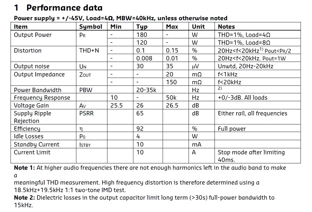
Parameters as declared by the manufacturer
Now it will be my goal to measure what I get from the module in my amplifier setup.
Amplifier setup
The amplifier was built in one of my prototype cases (Fig.4).
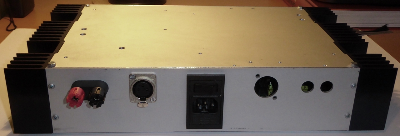
Fig.4. Prototype case to test the module
It has side heatsinks and pre-drilled holes for speaker binding posts, XLR input connector and 230Vac input plug with switch and fuse. Case dimensions are 376 x 216 x 70 mm. Wiring can be seen in Fig.5. Transformer Tr is 230V~/2x32V~/100VA and it will, unfortunately, restrict the maximum power of the amplifier. DRC is a bridge diode rectifier with capacitor bank 2 x 11500uF. 230Vac input plug is 3-pin with PE pin connected directly to the metal case. XLR input connector has pin 1 connected via 47nF/1kV foil capacitor connected to the metal case. I know it would be optimal if it was directly connected to the case, however only if all audio components in the chain were properly built this way. This is unfortunately not the case and the DACs and soundcards used have pin 1 connected to PCB analog ground and in case of 2 class I components interconnected the balancing ground current flows between 2 different PE plug pins and in my case it makes as much as 30mA between 2 rooms. Then, CMR of the audio components plays a considerable game. As the amp has only one signal connector, no further PCB ground current is created except for that through the transformer stray capacitance and this current is low enough to create any issues. The photo below (Fig.6) shows the real amplifier layout and wiring. The detailed photo of the UcD module is in Fig.7.
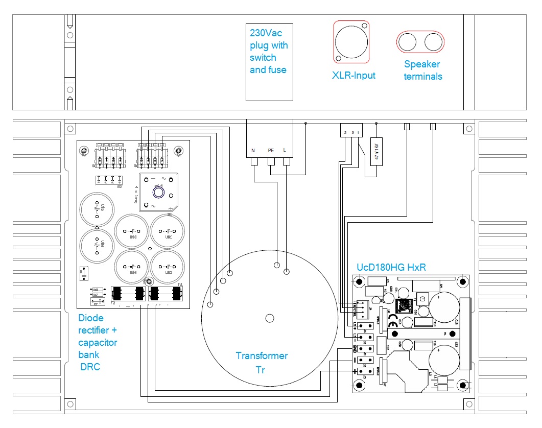
Fig.5. Internal wiring block diagram
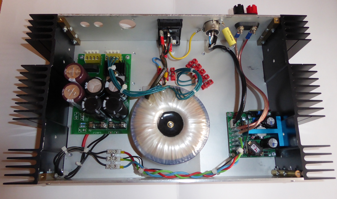
Fig.6. Real amplifier layout and wiring
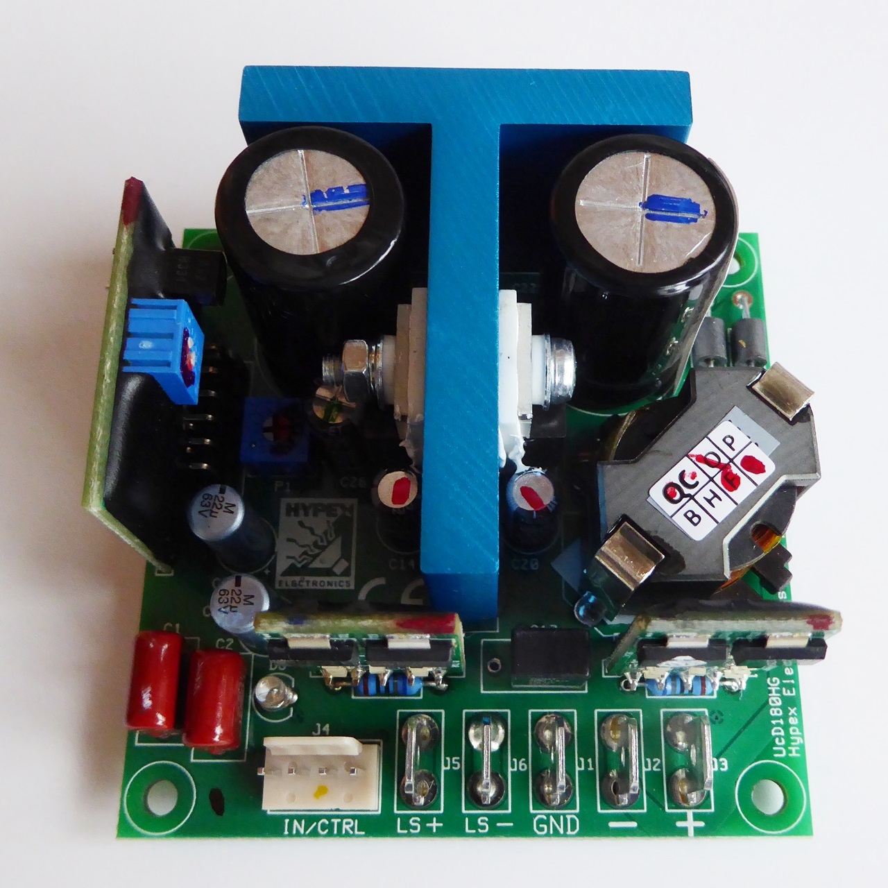
Fig.7. UcD180HG HxR module
Measurements
Switching frequency was measured as 422kHz with 372mV amplitude, see Fig.8
Fig.8. Switching frequency residuals
Frequency response (Fig.9)
Frequency response was measured from 20Hz to 40kHz and is almost independent of load impedance, a stated correctly by the manufacturer. And there is no peaking.
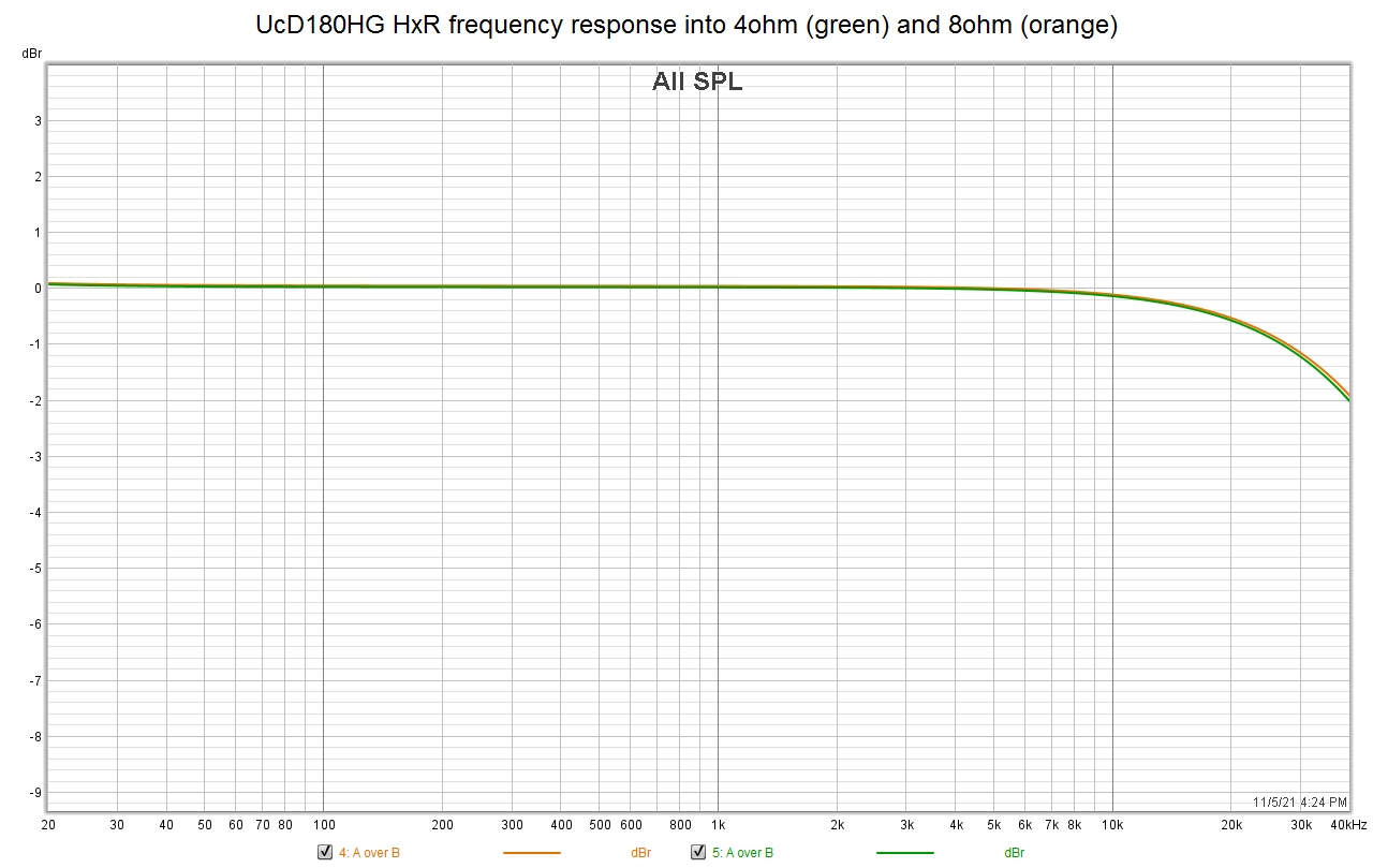
Fig.9. Frequency rsponse into 4ohm and 8ohm load
THD and THD+N
Distortion plots vs. power are shown below, measured at 20Hz, 1kHz and 6kHz. Please note they are almost independent of signal frequency. Maximum power is limited by the 100VA transformer in the linear power supply. The amplifier gave 130W/4ohm/1kHz with THD+N = 1%.
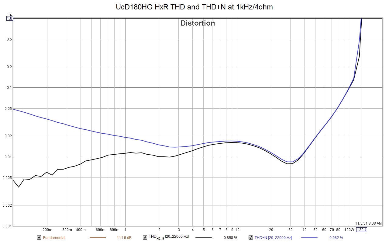
Fig.10.
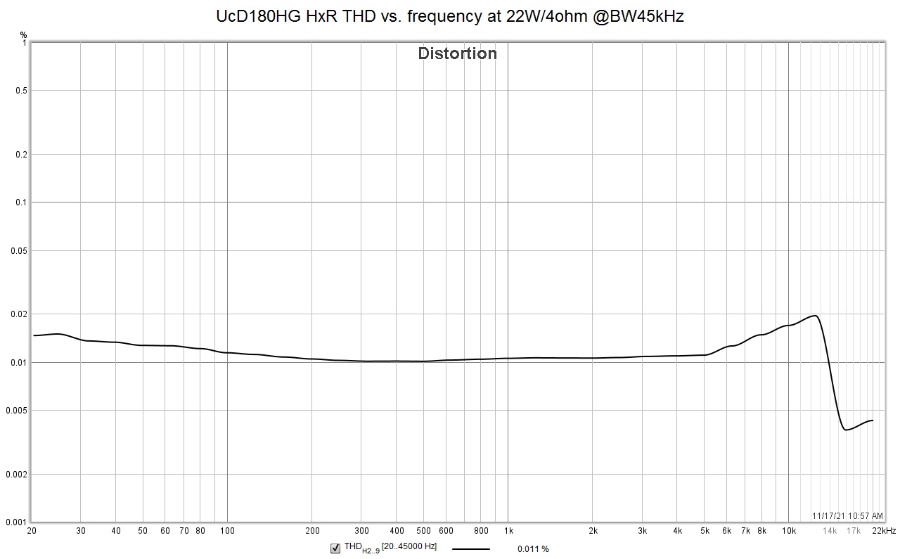
Fig.11. THD vs. frequency at 22W with 4ohm load and 45kHz measurement bandwidth
CCIF intermodulation distortion 19+20kHz
was measured 0.024% at 20W/4ohm
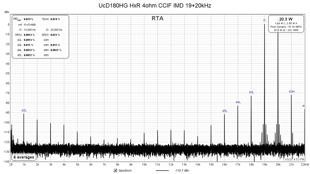
Fig.12.
Thermal management
In a long term continuous sine test 45W/4ohm the side heatsink remained almost cold to touch and the module heatsink was mildly warm to touch. No thermal issues with the case and heatsink used.
Conclusion
Hypex UcD180HG HxR module is an older class D circuit solution which cannot compete in distortion parameters with Ncore or Purifi, however it has several very interesting features. It is a simple circuit, price is about 1/3 of NC400, it has frequency response independent of load impedance and nonlinearity almost independent of frequency. These are features I appreciate much and I have to say I like this module.
Literature
[1] Hypex UcD180HG_datasheet_R5
[2] Putzeys, B.: Simple self-oscillating class D amplifier with
full output filter control. AES 118th convention, 2005