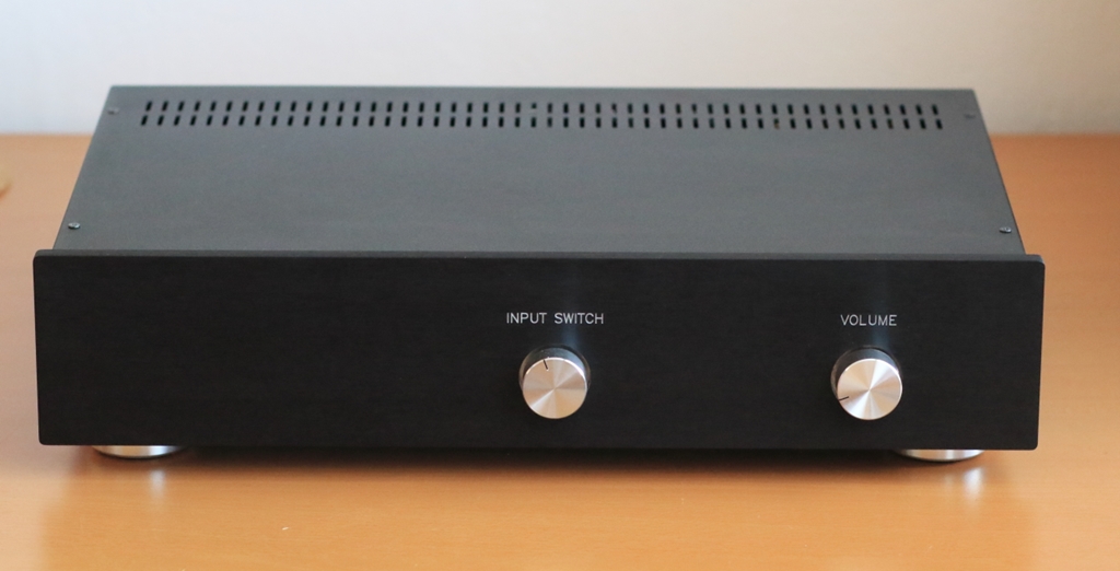
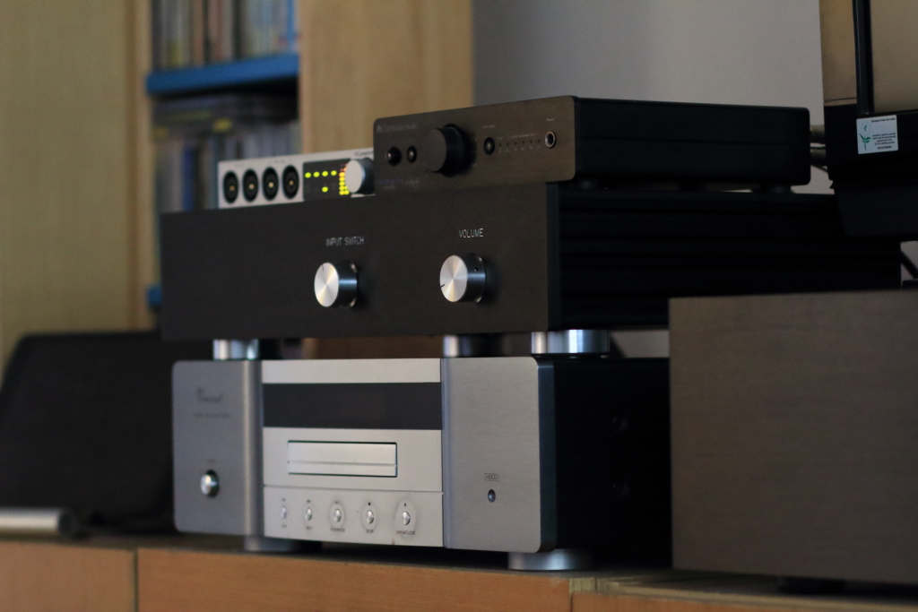
I needed a preamp with several single ended and balanced inputs, so it was a challenge during this strange pandemic times to design and make a new audio toy that would satisfy my needs. You can see the result sitting between the Vincent CD player and DacMagicPlus D/A converter, in the next photo.
Design goals
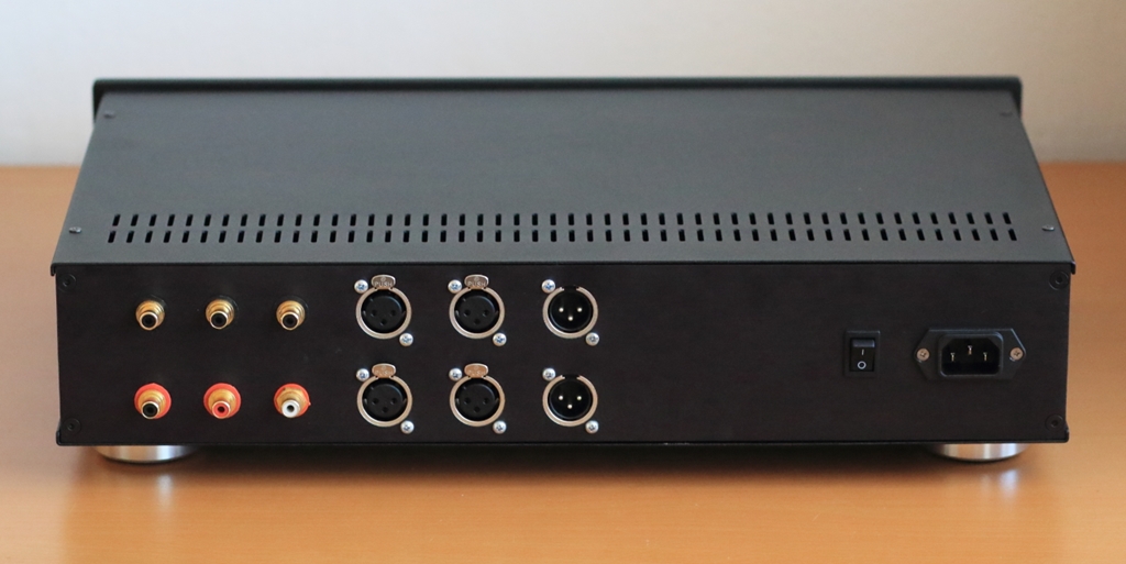
- 3 single ended, 2 balanced inputs
- 1 balanced output usable as a single ended output as well
- very wide bandwidth that would not degrade hi-res sources
- excellent immunity to input HF and EMI
- considerable reduction of HF interference content arriving from digital signal sources
- high output current and ability to drive 600 ohm load impedance
Circuit design
To fulfill the goals stated here above, the following circuit was designed
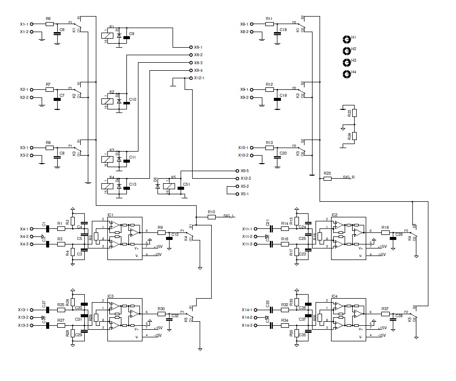
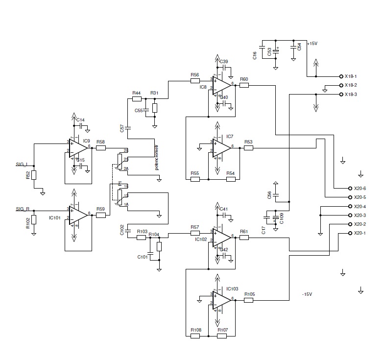
The inputs are switched by high quality relays. Single ended inputs go, after input RC filtration, directly to input buffer (IC9, IC101). Balanced inputs go, after common mode and differential RC filtration, to instrumentation amplifiers (IC1 – IC4) and then to the input buffer. Volume control (P1, blue Alps 2x10k/log) is connected behind the input buffer and effectively reduces noise of the preceding integrated circuits at lower volume settings. This is important to get the best S/N at low volume settings.
IC7, IC8, IC102 and IC103 are the output stage opamps. All the opamps used have very high BW and slew rate. The slowest parts are the instrumentation amplifiers at balanced inputs wit slew rate of 15V/us, which is, to my measures, quite low value. They are protected from very high frequency input signals by input common mode and differential RC filters.
I do emphasize the speed of the opamps for the reason that IME the influence of input EMI is just the reason of different sound of different opamps.
Photo of preamp construction
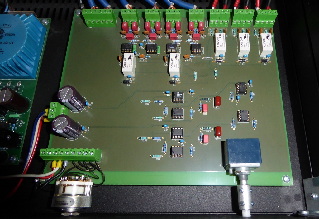
This is the completely assembled box with wiring. One can see 2 power supplies, one for the electronics and the second one for relays. This reduces interference coupling from relay coils to the signal path. There is a common ground point for these 2 power supplies.